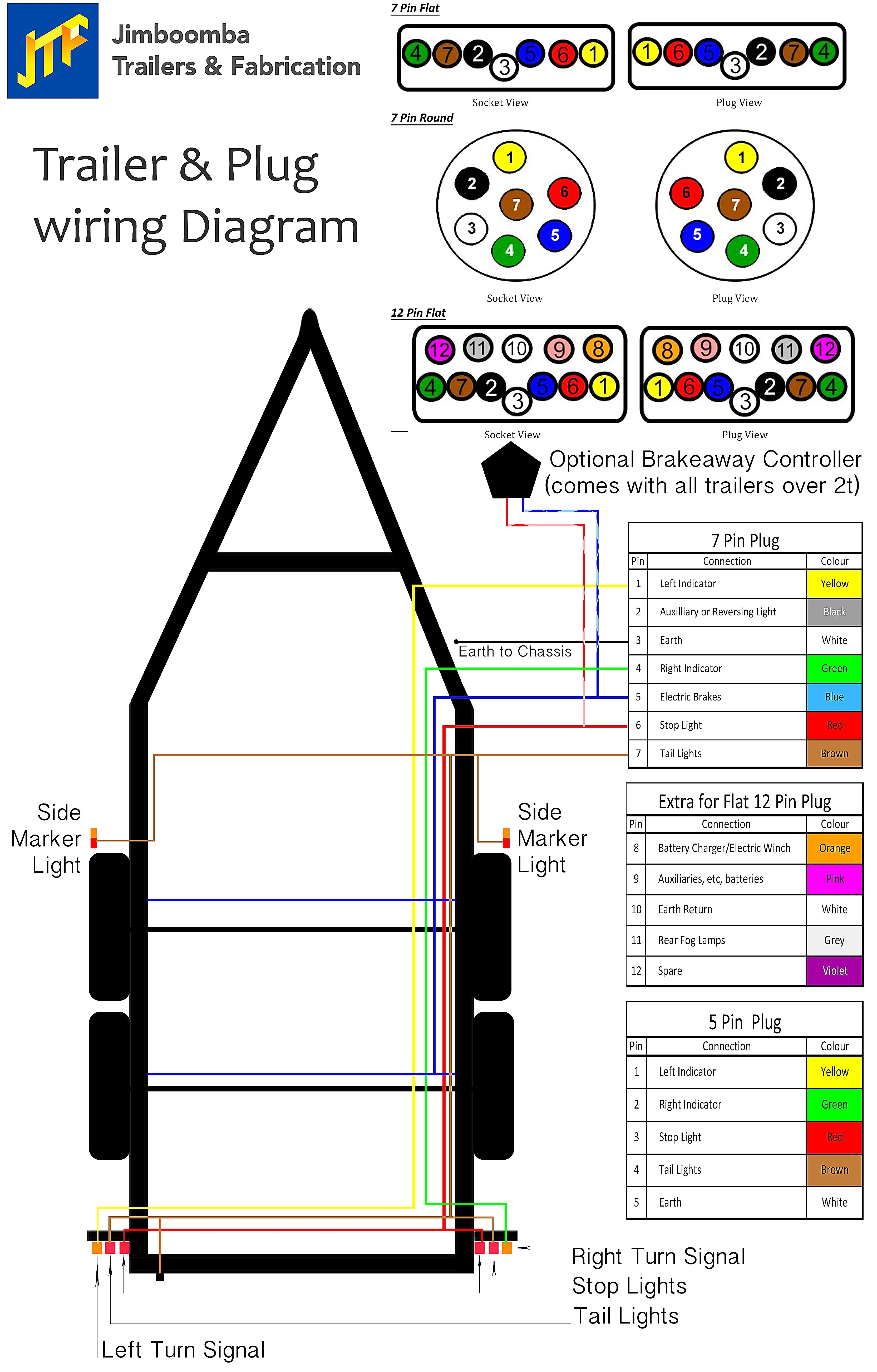
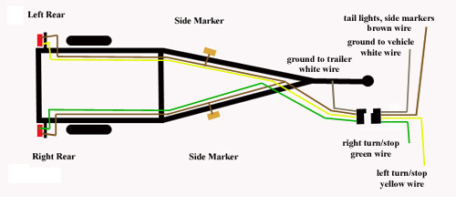
Standard 4 Wire Trailer Wiring Diagram
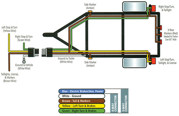
Connect brown wire to vehicle tail light wire, yellow wire to vehicle left stop and turn wire and green wire to vehicle right stop and turn wire. There’ll be main lines which are represented by l1, l2, l3, and so on.
Flat Four Trailer Wiring Diagram Trailer Wiring Diagram

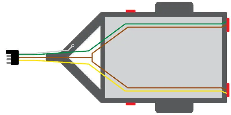
You should have 3 wires at the rear of your led light or from a pigtail like part a47pb that plugs into a light like part stl22rb.

Standard 4 wire trailer wiring diagram. 7 way trailer plug wiring diagram ford f250. Some vehicles send only one signal per wire. Attach white ground wire to vehicle frame.
The four wires control the turn signals brake lights and taillights or running lights. The trailer wiring diagram shows this wire going to all the lights and brakes. 7 way trailer wiring diagram is explained in details in the picture and the table below:
Trailer wiring diagrams trailer wiring connectors various connectors are available from four to seven pins that allow for the transfer of power for the lighting as well as auxiliary functions such as an electric trailer brake controller, backup lights, or. Standard color code for wiring simple 4 wire trailer lighting question. Standard color code for wiring simple 4 wire trailer lighting question:
Basic 4 wire trailer wiring diagram. Basic 4 wire trailer wiring diagram by vallery masson updated on october 4, 2021 yellow and green are for left and right turns and braking. As the name implies, they use four wires to carry out the vital lighting functions.
Can also be used as custom wiring on trailers with 3 light wire systems. Trailer wiring diagrams 4 way systems 4 way flat molded connectors allow basic hookup for three lighting functions; As stated previous, the traces at a 4 wire trailer wiring diagram represents wires.
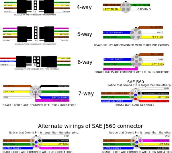
They also provide a wire for a ground connection. 7 way plug wiring diagram standard wiring* post purpose wire color tm park light green (+) battery feed black rt right turn/brake light brown lt left turn/brake light red s trailer electric brakes blue gd ground white a accessory yellow this is the most common (standard) wiring scheme for rv plugs and the one used by major auto manufacturers today. 4 way tow vehicle side.
However, it doesn’t mean connection between the wires. 7 way plug wiring diagram standard wiring post purpose wire color tm park light green battery feed black rt right turnbrake light brown lt left turnbrake light red s trailer electric brakes blue gd ground white a accessory yellow this is the most common. To ensure your trailer has safe, visible, and legal lighting, a trailer connector wiring adapter may be a necessary towing accessory.
At times, the wires will cross. A flat 4 plug for 4 wire trailers a flat 5 plug and a round 5 plug for 5 wire trailers. A wiring diagram is a streamlined standard photographic depiction of an electrical circuit.
Some trailer builders just connect this wire to the frame, then connect the ground from all the other lights and accessories to the frame as well. The basic purpose remains the same whether your truck and trailer is using a. *pins 2 and 5 are not used on our standard.
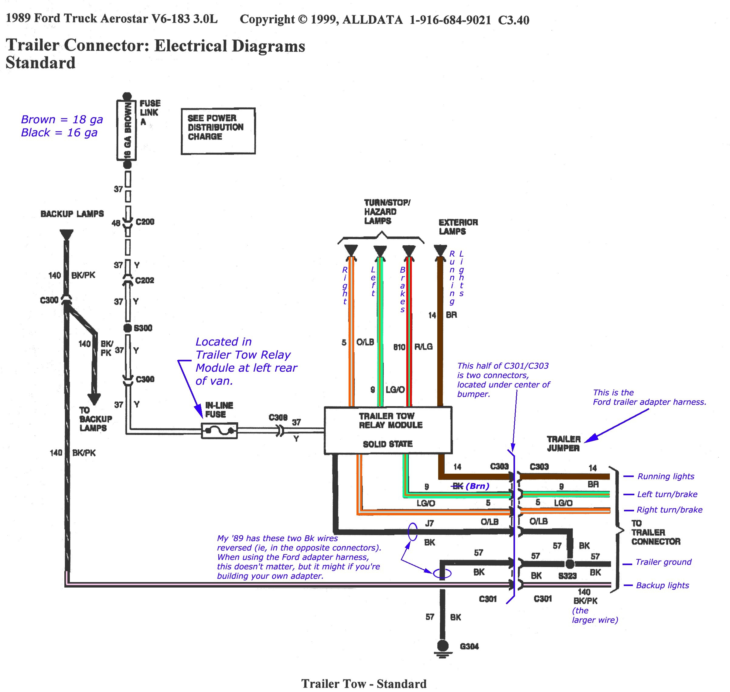
The four wires control the turn signals, brake lights and taillights or running lights. 7 blade (sae standard) 7 round 6 round vehicle side trailer side time to wire up or rewire your trailer? Below we have the wiring diagrams for both a 7 and 13 pin connector.
July 23 2021 wiring diagram. This is the view from the rear as you look at the terminals to wire the plug or socket. 4 pin trailer wiring diagram.
It shows the electric powered circuits parts as simple shapes, together with the genuine power and floor links between them as coloured communities. Blue electric brakes or hydraulic reverse disable see blue wire notes below in the trailer wiring diagram and connector application chart below use the first 5 pins and ignore the rest. Standard trailer plug wiring diagram.
Injunction of two wires is generally indicated by black dot in the intersection of 2 lines. There are two things which are going to be found in almost any 4 pin trailer connector wiring diagram. It symbolizes the electrical circuits factors as easy shapes, using the genuine power and soil relationships between them as colored groups.
Once all connections are done hook up the trailer and plug in the lights to make sure they all work. This is not shown in the trailer wiring diagram above. Right turn signal / stop light (green), left turn signal / stop light (yellow), taillight / license / side marker (brown) and a ground (white).
I have had to mess with trailer wiring for years, once or twice a year anyway, and i just cannot keep the color code right, ect white/ground, brn/ running lights, grn/ right turn, yellow left turn?
How To Wire Trailer Lights 4 Way Diagram Fuse Box And Wiring Diagram

4 Wire Trailer Wiring Diagram Troubleshooting Wiring Diagram
How To Wire Trailer Lights 4 Way Diagram Fuse Box And Wiring Diagram

Pj Trailer Wiring Diagram — UNTPIKAPPS

Wiring Diagram Trailer Wiring / 4 Wire Trailer Wiring Diagram For Lights Wiring Forums It
6 Wire To 4 Wire Trailer Wiring
How To Wire Trailer Lights 4 Way Diagram Fuse Box And Wiring Diagram

Trailer Light Wiring Diagram 4 Wire Database Wiring Diagram Sample

Trailer Wiring 101
Trailer Flat Four Wiring

Jeep Cherokee Towing Trailer Wiring Diagrams & Information

Wiring Guides Trailer light wiring, Trailer wiring diagram, Utility trailer

4 Pin 7 Pin Trailer Wiring Diagram Light Plug House Electrical Wiring Diagram

4 Wire Trailer Wiring Diagram Troubleshooting Cadician's Blog
4Way Flat 25ft Male 4ft Female Wishbone Style Trailer Wiring Harness ACCEPSCBL0105

Wiring A Boat Trailer For Brakes And Lights
Trailer Wiring Guide

Trailer Wiring Diagram and Installation Help Towing 101
4 Wire Trailer Wiring Diagram For Lights Wiring Forums
